OBD-II vs CAN Bus Data Extraction: What Fleet Operators Need to Know
Apr 24, 2026 Resolute Dynamics
TL;DR: OBD-II gives you a standardized, plug‑and‑play way to grab core engine and emissions data from a simple 16‑pin port.
It is predictable and easy to scale. Direct CAN bus access lets you dig into the vehicle’s nervous system in real time, with access to thousands of ECU signals, but it brings along OEM‑specific decoding work, tighter security requirements, and a more complex rollout.
Key Takeaways
- OBD-II follows the SAE J1979 standard and exposes roughly 200 standardized PIDs through the 16‑pin diagnostic port. That makes it ideal for plug‑and‑play fleet telematics across mixed light‑duty vehicles.
- CAN bus, defined by ISO 11898, is the in‑vehicle network that all ECUs use to talk to each other. With proper decoding, fleets can reach thousands of signals on each vehicle instead of a few dozen.
- J1939 is the dominant heavy‑duty CAN standard used on trucks, buses, and off‑highway machines. It defines common PGNs that fleets can rely on for cross‑brand heavy‑duty data.
- OBD-II is usually the best fit for mixed light‑duty fleets that want fast installs and basic KPIs. Direct CAN taps are better for single‑make or engineered fleets that need rich, real‑time operational data.
- CAN bus extraction demands DBC database files, arbitration ID maps, smart message filtering, and heavier normalization work before data is useful at fleet scale.
- Security is not optional. Both OBD-II and CAN paths have to be hardened against injection, spoofing, and unauthorized ECU access, usually with help from a CAN security gateway and OEM security controls.
- A hybrid approach that combines OBD-II, CAN, and J1939 through a multi‑protocol module usually gives the best coverage and ROI on mixed fleets.
- The Resolute Dynamics Connect module hides much of this complexity. It abstracts these protocols, normalizes the data, and feeds it into the Capture‑Connect‑Control ecosystem for analytics, control, and automation.
Quick Definitions: OBD-II, CAN Bus & J1939
What is OBD-II?
OBD-II (On‑Board Diagnostics II) is a regulated diagnostic interface and 16‑pin connector fitted to most light‑duty vehicles. Under SAE J1979, it defines how to request standardized engine and emissions data and how Diagnostic Trouble Codes (DTCs) are reported.
For fleets, this is the “common language” that lets the same telematics unit work on different OEMs with minimal tweaking.
What is CAN bus?
The Controller Area Network (CAN bus) is a real‑time network, described by ISO 11898, that connects ECUs such as engine, transmission, brakes, ADAS, and body control.
Messages carry 11‑bit or 29‑bit arbitration IDs and typically run at 250 or 500 kbps. Think of it as the shared wiring where every ECU puts its status and commands on the same “party line.”
What is SAE J1939?
SAE J1939 is a higher‑level protocol built on top of CAN for heavy‑duty platforms like trucks, coaches, agricultural machines, and construction equipment.
It defines standard Parameter Group Numbers (PGNs) and SPNs so engines, transmissions, and brakes from different brands can be monitored and controlled using a common vocabulary.
OBD-II vs CAN Bus: Core Protocol Differences Explained
In practice, these two are stacked together. On most modern light‑duty vehicles, OBD-II messages ride over CAN using ISO 15765 (CAN‑based OBD). So OBD-II defines what you can legally ask for and how to format the query. CAN defines how the bits get from one ECU to another. You usually end up touching both, even if you think you are “only doing OBD-II.”
What OBD-II Gives You (Standardized PIDs)
OBD-II came about because regulators wanted a consistent way to monitor emissions and basic engine health. The SAE J1979 OBD-II standard nails down three things that matter to fleets:
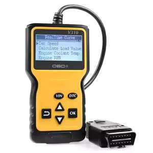
- A consistent 16‑pin diagnostic connector (DLC), typically under the dash on the driver’s side.
- A set of modes that define the type of request, like Mode 01 for live data and Mode 03 for trouble codes.
- PIDs (Parameter IDs) that describe what you are asking for, such as RPM or coolant temperature.
Common Mode 01 PIDs most fleets lean on include:
- Vehicle speed
- Engine RPM
- Coolant temperature
- Short‑ and long‑term fuel trim
- Intake manifold pressure or MAF
- Throttle position
- Oxygen sensor data and related fuel feedback
On paper there are about 200 standardized PIDs. In real deployments, each vehicle only supports a subset, and only a fraction of those end up useful for fleet analytics. Telematics units, often built around chipsets similar to the ELM327 OBD adapter, cycle through their target PID list several times per second and decode responses into engineering units.
Key attributes of the OBD-II diagnostic protocol for fleets:
- Standard: SAE J1979 (with some regional tweaks like EOBD in Europe)
- Connector: Fixed 16‑pin layout, easy to find and access
- Standardized PIDs: Roughly 200 defined, fleets usually use around 20–60
- Effective data rate: Limited by request/response polling on top of the underlying bus, which may be 250 or 500 kbps CAN
- Coverage: Light‑duty gasoline vehicles in the US from 1996 on, most diesels from 2008 on, with similar timelines elsewhere
- Deployment complexity: Low. Plug the dongle in, provision it, and you are collecting usable data.
For OBD-II fleet telematics, the upside is obvious if you are trying to scale quickly:
- Regulations force OEMs to support a common minimum set of parameters.
- Install is usually a 5‑minute job, no tools, no trim removal.
- It behaves consistently enough that you can support a mixed, multi‑brand light‑duty fleet with one hardware SKU.
What CAN Bus Gives You (Raw ECU Data)
The CAN bus protocol under ISO 11898 is what the vehicle actually lives on all day. Every ECU is constantly publishing sensor values and control commands, whether anyone is listening externally or not.
From a fleet standpoint, CAN has some important traits:
- Standard: ISO 11898‑1/2 defines the physical and data link layers.
- Data rates: Commonly 250 kbps on heavy‑duty J1939 networks and 500 kbps on many light‑duty high‑speed CAN segments. Some use 1 Mbps on short segments.
- Message formats:
- Standard frames with an 11‑bit arbitration ID.
- Extended frames with a 29‑bit arbitration ID.
- Visibility: Potential access to engine, transmission, brakes, steering, ADAS, body, HVAC, infotainment, and more.
- DBC requirement: Each make/model needs one or more DBC database files that map arbitration IDs and bit positions into named signals with proper scaling.
- Deployment complexity: High. You either get documentation from the OEM, license third‑party libraries, or reverse‑engineer the bus.
By passively listening on the CAN bus, you can see far more than OBD-II exposes. Typical extra signals include:
- Steering angle and torque, useful for driver behavior and ADAS validation.
- Individual wheel speeds, brake pressure, and ABS events.
- Transmission gear selection, clutch status, and torque transfer.
- Battery state of charge (SOC), state of health (SOH), and cell voltages on EVs and hybrids.
- ADAS features like lane keeping, adaptive cruise status, and automatic emergency braking triggers.
- Body signals such as door status, seat belts, and airbag readiness.
Without the right DBC file decoding, though, that traffic is just a stream of hex values, message IDs, and timestamps. That is why engineering teams rely on tools like Vector CANalyzer, Peak PCAN, or the Linux socketCAN interface while they build up signal maps.
For live fleets, you cannot ship raw CAN dumps to the cloud and call it a day. You need automated decoding, normalization, and quality checks at scale.
Data Depth Comparison: What Each Protocol Reveals
From a fleet analytics lens, the real question is simple: what decisions are you trying to support, and how much detail do those decisions truly need? Extra data is only helpful if you have a use for it and a plan to maintain it.
OBD-II Data Depth for Fleets
OBD-II lines up nicely with the everyday KPIs most operators want to track:
- Odometer (where supported) and vehicle speed for utilization, routing, and billing.
- Engine RPM and load for monitoring harsh driving and unnecessary idling.
- Fuel system status, fuel trims, MAF/MAP, and similar for fuel economy analysis.
- Coolant temperature and intake air temperature to catch basic thermal issues before they strand a driver.
- DTCs (Diagnostic Trouble Codes) to trigger maintenance tickets instead of waiting for drivers to report a MIL light.
For many mixed light‑duty fleets such as service vans, passenger cars, and small trucks, this supports:
- Route planning and dispatch decisions.
- Safety scoring around speeding, harsh acceleration, and idle time.
- Preventive maintenance scheduling and inspection plans.
- Basic emissions compliance checks and recordkeeping.
Where OBD-II starts to fall short is on more advanced analytics. You will not usually see true brake pressure, corner‑specific wheel data, detailed EV pack information, or the nuanced status of ADAS features.
As vehicles become more software‑defined, those richer signals often live on CAN but never surface in an OBD-II PID.
CAN Bus Data Depth for Fleets
With direct access to the CAN 2.0B protocol at 250 or 500 kbps, you can monitor practically everything the ECUs are talking about. After decoding with DBC files, you gain visibility into:
- Chassis dynamics: steering angle, yaw rate, lateral and longitudinal acceleration, wheel slip.
- Braking: brake pedal position, line pressure, ABS activation, brake blending behavior on hybrids and EVs.
- Powertrain: requested torque, delivered torque, gear position, clutch state, engine derate conditions.
- Battery and energy: SOC, SOH, current, pack voltage, individual cell voltages and temperatures, charge limits.
- Safety systems: stability control events, airbag readiness, pre‑crash system status.
- ADAS: control mode states, lane models, radar/vision target info, warning and intervention flags.
Fleets that care about:
- Monitoring ADAS performance and driver interaction.
- Predictive maintenance on costly subsystems like braking or transmissions.
- Protecting high‑value vehicles where unplanned downtime is extremely expensive.
- R&D, pilot programs, or validation work on new platforms.
often find that this deeper view into CAN pays off quickly. You can catch issues earlier, prove or disprove hypotheses with data, and justify engineering decisions with hard numbers instead of guesses.
EAV Comparison: Fleet Telematics Data Extraction
The table below puts typical OBD-II extraction and direct CAN extraction side by side so you can see where each one makes sense at scale.
| Attribute | OBD-II Extraction | Direct CAN Extraction |
|---|---|---|
| Install time | Minutes. Plug‑in dongle at OBD-II port. | Hours. Harness work, validation drives, and often some dash disassembly. |
| Typical data parameters | Roughly 20–60 commonly used PIDs out of ~200 defined. | Hundreds to thousands of signals, depending on ECU count and decoding depth. |
| Normalization requirement | Low. PIDs are standardized under SAE J1979, so one mapping applies widely. | High. Needs per‑OEM and often per‑model DBC files, version tracking, and careful mapping. |
| Fleet deployment complexity | Low. Works on most post‑1996/2008 vehicles with little engineering. | High. Requires vehicle‑specific engineering and ongoing maintenance as models and firmware change. |
This split in data depth also shapes how you design downstream analytics pipelines and how aggressively you use edge preprocessing of CAN data. Once you start listening to everything on a high‑speed CAN bus, you quickly learn why raw logging is a bad idea at scale.
How Fleet Telematics Devices Extract Vehicle Data
Under the hood, both approaches follow the same basic pipeline:
- Make a physical connection to the vehicle bus.
- Identify which protocol and speeds are in use.
- Pull data, either by polling (OBD-II) or passively receiving (CAN).
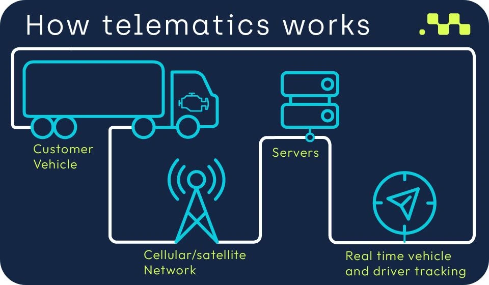
- Translate raw bytes into usable engineering values.
- Send those values out over cellular or Wi‑Fi into your cloud or edge analytics stack.
OBD-II Plug-and-Play Extraction
Most light‑duty deployments start with OBD-II devices such as the Geotab GO or Samsara AG46. Teams like them because a technician, or even a driver, can handle install.
- Physical connection: Plug the telematics device into the 16‑pin OBD-II DLC. On some vehicles you may add an extension cable or Y‑cable if the port also needs to be available for service tools.
- Protocol detection: The device probes for supported protocols like ISO 15765‑4 CAN, older ISO 9141, or KWP2000 and settles on the right baud rate and framing.
- PID request cycle: It sends OBD-II requests such as Mode 01 / PID 0C for RPM or PID 0D for speed, waits for responses, then repeats that loop at a configured frequency.
- DTC retrieval: On a slower schedule, it asks for Mode 03 (stored DTCs) and sometimes Mode 07 or 0A for pending and permanent fault codes.
- Normalization: Raw bytes are turned into recognizable units like km/h, °C, and percent, then lined up with the fleet’s standard data fields.
- Transmission: Batched or streamed data is sent over cellular to the backend. From there it feeds dashboards, alerts, and APIs.
OBD-II is the right fit when:
- You need fast rollout across a large, mixed light‑duty fleet.
- You can live with “good enough” data rather than every possible ECU signal.
- Your main focus is routing, utilization, and straightforward maintenance triggers.
Direct CAN Bus Tap & DBC Decoding
For deeper visibility, you tap straight into CAN. That can be done in a couple of ways in real fleets:
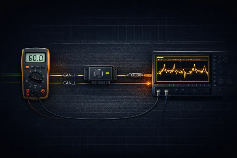
- Using a breakout harness at the OBD-II connector to access CAN High/Low while ignoring the OBD-II request/response layer.
- Wiring directly into CAN High/Low at a convenient point behind the dash, near a gateway module, or near a specific ECU.
Once you are physically on the bus, the flow looks more like this:
- Passive sniffing: The device listens to everything on the CAN bus at the configured baud rate, usually 250 or 500 kbps.
- Message filtering: Using message filtering masks, it whitelists or blacklists arbitration IDs to cut noise and reduce processing load.
- DBC file decoding: For each vehicle, a DBC database file or set of them defines:
- Which arbitration IDs hold which groups of signals.
- Where in the payload each signal lives (bit start, length, endianness).
- How to scale and offset the raw values to engineering units.
- Acceptable ranges and preferred units.
- Normalization: Decoded signals are converted into a common schema across models. That way “steering_angle_deg” means the same thing whether you are looking at a delivery van or a Class 8 tractor.
- Edge logic: Local rules throttle, compress, or summarize the data so you are not paying to stream every frame on a busy bus.
During early stages, engineering teams will lean heavily on Vector CANalyzer, Peak PCAN interfaces, and Linux socketCAN to sniff, label, and validate those signals. Once the mappings are locked, the telematics firmware can run the decoding with no human watching.
Two technical dials matter a lot at this layer:
- Baud rate: Usually 250 kbps for J1939 and 500 kbps for many light‑duty high‑speed CAN buses. Getting this wrong means no data.
- Arbitration ID: The 11‑bit or 29‑bit ID that acts like both an address and a priority marker. Understanding how an OEM structures these is key to good filtering.
J1939 Heavy-Duty Protocol
SAE J1939 rides on top of CAN but adds a common language that heavy‑duty OEMs mostly stick to. For fleets, this is a blessing compared with light‑duty proprietary CAN.
- Vehicle type: Used across trucks, buses, agricultural and construction gear, and heavy‑duty engines in various equipment.
- Data rate: Commonly 250 kbps on the backbone; some variants run faster on local segments.
- PGNs: Each Parameter Group Number bundles related SPNs (signals) such as engine speed, torque, or brake information.
- Standardization: High across heavy‑duty brands, so one PGN/SPN map often works across multiple OEMs with only minor differences.
- Fleet adoption: It is effectively the default language for commercial heavy‑duty telematics and diagnostics.
For heavy‑duty fleets, J1939 lets you read out things like:
- Engine hours and total fuel used, which are critical for maintenance planning.
- Cruise control usage to understand driver habits.
- Retarder and brake application to catch abusive driving or spec mismatches.
- Axle weight readings on vehicles equipped with the right sensors.
Because these PGNs are standardized, J1939‑capable devices often just need a reasonable default configuration and some minor OEM‑specific tuning instead of a full reverse‑engineering effort every time a new truck shows up.
Security Risks of Vehicle Data Extraction
As soon as a vehicle is always connected and part of a bigger platform, security stops being someone else’s problem. It has to be part of the plan from the start, not a patch after an incident.
Risks Around OBD-II Access
The OBD-II port was originally designed for short visits from a diagnostic tool, not permanent telematics hardware. Keeping a device plugged in changes the threat model.
- Physical access risk: Anyone who can get into the cabin can unplug your device, plug in theirs, or put a man‑in‑the‑middle between your hardware and the port.
- Unauthorized ECU commands: Some vehicles allow OBD-II commands that actuate components or clear DTCs. If you do not lock that down, a malicious tool could send commands you never intended.
- Firmware update channel: On a number of architectures, the OBD-II link is involved in ECU flashing. If there is no proper signing or authentication, that can become a door for rogue firmware.
In fleet environments, it is common to see tampering when drivers try to defeat tracking or skirt rules. So you need more than just a physical plug. You need monitoring, alerts for disconnects, and policies around who is allowed to touch that port.
CAN Bus Injection and ECU Spoofing
Direct CAN access carries its own set of headaches if left wide open.
- CAN injection attacks: A compromised device can transmit forged frames with high‑priority IDs, pushing legitimate control messages aside on older, unsegmented networks.
- ECU spoofing: An attacker can mimic a real ECU and feed fake speed, torque, or fuel usage data, which can distort analytics, impact billing, or complicate warranty cases.
- Denial of service: Filling the bus with garbage messages can slow or block traffic that controls brakes, steering, or powertrain, depending on how the system is partitioned.
Older vehicles that lack proper segmentation and firewalls are more exposed. Many newer platforms, though, include a CAN bus security gateway that stands between external ports and the safety‑critical segments.
CAN Bus Security Gateway for Fleets
A CAN bus security gateway is usually a dedicated ECU that filters traffic between diagnostic/infotainment networks and the drive‑critical CAN networks.
- Function: Separate the “dirty” side (OBD-II, aftermarket devices, infotainment) from the “clean” drive networks.
- Protocol controls: Enforce message‑level rules for what PIDs, PGNs, or messages can pass, in which direction, and at what rate.
- Attack prevention: Block unsupported commands, filter spoofed messages, rate‑limit diagnostics, and keep untrusted devices from directly issuing control messages.
- Fleet need: Increasingly required for any serious connected program, especially with factory‑fitted telematics.
- Cost: When built in at OEM scale, the added unit cost is usually modest. Retrofitting older vehicles is more expensive and more invasive.
From a fleet perspective, you should be asking your vendors clear questions:
- Is there a security gateway between our telematics hardware and the drive CAN?
- Which messages are whitelisted for read and which (if any) are allowed to transmit?
- How are diagnostic and firmware actions authenticated and logged?
UDS, Authentication, and Secure Boot
Many modern vehicles rely on UDS (Unified Diagnostic Services) running over CAN or Ethernet for deep diagnostics and flashing. UDS supports security levels with challenge‑response authentication so that only authorized tools can access sensitive services.
Combine that with secure boot at the ECU level and it becomes far harder to load unauthorized code or spoof an ECU at the firmware layer. From a fleet’s point of view, that means:
- Certain advanced signals and controls may only be accessible to authenticated tools with OEM‑approved keys.
- Telematics vendors have to play by those rules instead of looking for back doors around security gateways.
Any serious fleet rollout should include a security design review involving your telematics provider, your corporate security team, and, whenever possible, the OEM or body builder.
Which Approach Should Your Fleet Use? (Decision Framework)
You can think about the choice along three axes: fleet composition, use case depth, and engineering capacity.
1. Fleet Composition
- Mixed light‑duty, lots of OEMs and trims: An OBD-II‑first approach wins almost every time. Chasing proprietary CAN mappings across dozens of models turns into a never‑ending project.
- Single‑make or a small set of OEMs: Direct CAN decoding starts to make sense. The upfront work on DBCs spreads across many units of the same spec.
- Mostly heavy‑duty equipment: J1939 over CAN is already the standard. Your decision is more about which telematics partner handles J1939 best rather than protocol choice itself.
2. Use Case Depth
Do not chase every possible CAN signal unless there is a business driver behind it. Match the method to the outcome you care about:
- Routing, utilization, and baseline maintenance: OBD-II data such as GPS, speed, RPM, and DTCs will usually cover this.
- Driver safety and incident reconstruction: OBD-II goes partway, but adding CAN‑level signals such as brake pressure and steering angle gives a much clearer picture of what happened before an event.
- EV battery health and warranty risk: You almost always need CAN‑level SOC, SOH, and sometimes cell‑level readings if you want to make real decisions about pack health.
- R&D, advanced analytics, and ADAS programs: These are classic use cases for full CAN visibility rather than just OBD-II snapshots.
3. Engineering and Operations Capacity
Direct CAN is powerful, but it brings ongoing work, not just a one‑time setup.
- You have to maintain DBC files per vehicle variant and update them when OEMs change firmware or network layouts.
- You need regression testing whenever a new model year comes in or there is a campaign that touches ECU software.
- You may have to deal with multiple CAN segments per vehicle, running at different baud rates and behind different gateways.
- You will spend time coordinating with OEMs, dealers, or integrators on access rights and security gateway behavior.
If you do not have strong internal automotive engineering or a trusted partner, starting with OBD-II or J1939 and only adding targeted CAN projects where they clearly pay off will usually keep risk manageable.
Comparison Table: OBD-II vs Direct CAN vs J1939
This table sums up how OBD-II, direct light‑duty CAN, and SAE J1939 stack against each other.
| Criteria | OBD-II | Direct Light-Duty CAN | SAE J1939 (Heavy-Duty) |
|---|---|---|---|
| Typical vehicles | Light‑duty cars, vans, SUVs. | Light‑duty fleets with limited OEM/model spread. | Heavy trucks, buses, off‑highway and industrial equipment. |
| Data depth | Medium. Around 200 PIDs defined, fewer actually useful. | Very high. Hundreds or thousands of decoded signals possible. | High. Standard PGNs give rich coverage of core systems. |
| Standardization | High, via SAE J1979. | Low. Each OEM’s CAN map is proprietary and can change over time. | High, via SAE J1939 PGNs and SPNs. |
| Install complexity | Low. Plug‑in device, usually no wiring work. | High. Tapping harnesses, routing cables, validation drives. | Moderate. You typically use existing connectors but must access the backbone properly. |
| Fleet scale suitability | Excellent for mixed light‑duty fleets. | Best in standardized fleets or engineering‑heavy environments. | Excellent choice for heavy‑duty fleets. |
Hybrid Approach for Mixed Fleets
Most large operators end up in the same place: a hybrid architecture that lets them pick the right tool for each job.
- OBD-II as the default for light‑duty passenger and service vehicles.
- J1939 CAN for heavy‑duty tractors, buses, and off‑highway assets.
- Selective direct CAN taps on EVs, specialized ADAS/AV development fleets, or high‑value test beds.
A multi‑protocol module such as the Resolute Dynamics Connect module allows you to offer a single upstream interface to your data platform while quietly handling these different protocols and decoding strategies under the hood.
How Resolute Dynamics Extracts and Normalizes Fleet Data
The goal is simple: let fleet and platform teams focus on using the data instead of wrestling with every OEM’s network quirks.
Multi-Protocol Support: OBD-II, CAN, J1939
The Connect module is built for mixed fleets rather than a single brand program.
- OBD-II: It implements the full SAE J1979 OBD-II standard, including PID discovery and DTC reads. Common fleet metrics are abstracted so the same dashboard works on different OEMs.
- Generic CAN: It attaches to ISO 11898 CAN buses at 250 or 500 kbps, supports both 11‑bit and 29‑bit IDs, and can listen to several CAN segments in the same vehicle if needed.
- SAE J1939: It natively decodes J1939 PGNs and SPNs, then maps them into a shared schema that lines up with equivalent light‑duty fields wherever possible.
Automatic DBC Mapping and Vehicle Identification
One of the biggest ongoing headaches in CAN bus data logging for fleets is which DBC to use on which vehicle. Resolute’s approach is to automate that decision.
- Identify the vehicle through OBD-II VIN, J1939 identity information, or OEM‑specific CAN signatures and fingerprints.
- Link that identity to the correct DBC database file or combination of files pulled from a managed library.
- Track versions so when OEMs change firmware or network layouts, updated mappings are rolled out safely and predictably.
That allows a single normalized field such as “actual_vehicle_speed” to be sourced from:
- An OBD-II speed PID on a light‑duty sedan.
- A PGN/SPN combination in a J1939 heavy truck.
- A proprietary high‑speed CAN message inside an EV platform.
Real-Time CAN Filtering and Quality Control
Continuous raw CAN logging is something you might do in the lab, not in a production fleet. The Connect module trims that firehose down to what you actually need.
- Message filtering: Filter by arbitration ID and mask to focus on critical signal groups and ignore noise or irrelevant traffic.
- Rate limiting: Slow overly chatty signals to a rate that matches your analytics needs instead of pushing every frame at full bus speed.
- Anomaly detection: Apply range and consistency checks to catch wiring faults, failing sensors, or decoding errors before they pollute your datasets.
High data quality depends on careful sensor calibration for data accuracy, especially on fleets using this data for advanced modeling or control. Calibration and validation strategies become just as important as the decoding itself.
Normalized Output into the Capture-Connect-Control Ecosystem
After extraction and cleanup, the module pushes data into the Resolute Dynamics Capture‑Connect‑Control ecosystem.
- Capture: Handles secure ingestion from vehicles at scale, with buffering and retry logic for unreliable links.
- Connect: Manages protocol abstraction, DBC application, and alignment of OBD-II, CAN, J1939, and other sources into a unified data model.
- Control: Powers dashboards, APIs, rule engines, and control loops that act on normalized signals in near real time.
This setup is designed to plug cleanly into your existing fleet data cloud infrastructure, whether you are running a single cloud provider, multi‑cloud, or a hybrid environment tied into existing enterprise systems.
It also exposes a clear interface for future technologies such as V2X data integration. You can enrich vehicle data with infrastructure or roadside information without overloading the in‑vehicle hardware with extra responsibilities.
Common Mistakes in OBD-II & CAN Bus Data Extraction (and How to Avoid Them)
- Mistake 1: Assuming all OBD-II PIDs are supported the same way.
Issue: Different OEMs support different subsets of PIDs, and some interpret scaling or ranges differently from the textbook.
Fix: Always run PID capability discovery per vehicle, then cache that profile. Do not assume full support because a PID is in the standard. - Mistake 2: Treating CAN IDs as frozen across years and trims.
Issue: Firmware changes, new options, or mid‑cycle refreshes can all move signals around or change arbitration IDs.
Fix: Version your DBC files, regression‑test decoding when new builds appear, and watch for anomalies when vehicles come back from dealer software updates. - Mistake 3: Over‑polling and over‑talking on the bus.
Issue: Heavy OBD-II polling or chatty telematics devices can eat up bus bandwidth that control ECUs need, especially on older architectures.
Fix: Use passive listening where possible, keep OBD-II polling rates modest, and coordinate with OEMs or integrators about safe traffic budgets. - Mistake 4: Ignoring CAN bus security gateways until install day.
Issue: Plugging devices into heavily gated vehicles without understanding gateway rules leads to mystery missing data and risky workarounds.
Fix: Engage with OEMs or certified integrators early. Understand what the CAN bus security gateway allows, and get your device properly authorized. - Mistake 5: Skipping calibration and validation of decoded signals.
Issue: Using unverified values in dashboards or business logic can drive bad decisions, especially on things like fuel or torque.
Fix: Cross‑check key signals against trusted references such as dyno tests, reference instruments, or OEM tools. Set up ongoing data quality monitoring. - Mistake 6: Underestimating data volume from high‑rate CAN logging.
Issue: Continuous logging on a busy 500 kbps bus will chew through storage and bandwidth in a hurry.
Fix: Use edge filtering, compression, and event‑triggered high‑rate capture rather than raw always‑on logging. - Mistake 7: No clear ownership across teams.
Issue: IT, security, fleet ops, and engineering all assume someone else is managing protocol updates, security, and data quality.
Fix: Define clear roles, responsibilities, and SLAs. Treat vehicle data extraction as a shared service with proper governance.
FAQ: OBD-II vs CAN Bus Data Extraction for Fleets
1. Is OBD-II the same as CAN bus?
No. OBD-II is a diagnostic standard under SAE J1979 that defines a connector, message formats, and standardized parameters. CAN bus, under ISO 11898, is the physical and data link layer network that ECUs use to exchange messages all the time. Many modern vehicles implement OBD-II over CAN, but they are different layers in the stack.
2. Can I retrofit CAN-based data extraction to older fleet vehicles?
Often yes, but how hard it is depends on the age and architecture. If the vehicle already uses CAN internally, you can usually tap into it with the right hardware and decoding. Very old units might not use CAN at all, which limits you to OBD-II (if present) or external sensors around the vehicle. In practice, retrofit CAN projects tend to be one‑off engineering efforts per platform.
3. Is J1939 only for trucks?
SAE J1939 is primarily found in heavy‑duty trucks, buses, and off‑highway equipment, along with certain stationary engines and generators. Light‑duty vehicles almost always rely on proprietary CAN with OBD-II sitting on top for basic diagnostics rather than J1939 PGNs.
4. How does CAN bus reverse engineering work for fleets?
CAN bus reverse engineering usually involves logging CAN traffic while performing controlled actions like steady acceleration, braking, steering, or toggling switches. Tools such as Vector CANalyzer or Peak PCAN help you correlate changing bits with physical behavior. Over time you build a DBC file that describes those signals. For fleet operators, it is usually more efficient to work with partners that maintain and update these DBC libraries across many vehicles.
5. What about data privacy and driver consent?
Vehicle data can easily reveal where a driver has been, how they drive, and how the vehicle is being used. Fleets should publish clear policies, secure appropriate consents, and stay aligned with local privacy rules. Limiting access based on roles and only collecting the data you truly need are both smart practices.
6. Are OBD-II telematics devices less secure than direct CAN taps?
Not by default. Both OBD-II devices and CAN taps can be implemented in secure or insecure ways. The difference usually comes down to device hardening, encrypted communication, and how they are allowed to talk through the vehicle’s security gateway. Many OEMs prefer gating access through OBD-II because it is easier to control and audit.
7. How do costs compare between OBD-II and CAN-based extraction?
OBD-II solutions typically carry lower install and engineering costs because they use a standard connector and a common PID set. Direct CAN setups may require more expensive hardware, custom harness work, and ongoing DBC maintenance. For high‑value use cases like heavy‑duty uptime or advanced analytics, that added cost can be justified by reduced downtime and better decisions.
8. Can the same telematics hardware support OBD-II, CAN, and J1939?
Yes, provided it is designed from the start as a multi‑protocol module such as the Resolute Dynamics Connect module. Hardware with the right transceivers and firmware can talk OBD-II, raw CAN, and J1939, auto‑detect what is present on each vehicle, and apply the correct decoding so your backend only sees one clean interface.
9. Do I need specialized cloud infrastructure for CAN data?
You do not need a different cloud provider, but you do need an architecture that handles higher‑volume streaming data well. Time‑series storage, streaming analytics, and strong observability matter more once you start moving CAN traffic around. Good planning around multi‑cloud or hybrid deployments for fleet data can save a lot of rework down the road.
10. How does edge preprocessing relate to OBD-II and CAN extraction?
Edge preprocessing is the practice of cleaning, filtering, and summarizing data on the device itself before sending anything upstream. It is especially important for CAN bus data logging, where raw traffic can overwhelm both the network and the backend. Typical strategies include filtering by arbitration ID, down‑sampling high‑rate signals, and triggering short bursts of high‑rate logging only around interesting events.
Final Summary & Next Steps
For fleet operators, the choice between OBD-II vs CAN bus data extraction is about matching the tool to the fleet and the job. OBD-II offers a standardized, low‑friction path to core metrics across almost all light‑duty vehicles. Direct CAN, especially via SAE J1939 on heavy‑duty platforms, unlocks much richer operational detail but demands investment in decoding, security, and long‑term maintenance.
Most modern fleets get the best results by adopting a hybrid, multi‑protocol strategy that uses:
- OBD-II as the baseline for light‑duty deployment speed and basic analytics.
- J1939 as the standard for heavy‑duty and off‑highway assets.
- Targeted direct CAN taps on high‑value use cases such as EV packs, ADAS development fleets, and research vehicles.
The Resolute Dynamics Connect module and the broader Capture‑Connect‑Control ecosystem are built to shoulder the protocol and decoding complexity for you. They maintain DBC libraries, enforce security practices, normalize data across makes and models, and deliver clean streams to your analytics and control systems.
If you are planning a new telematics program or scaling an existing one, now is the time to align your protocol choices with your operational goals and data ambitions. The right design up front saves years of rework.
Talk to Resolute Dynamics about your fleet data strategy and how to roll out OBD-II, CAN, and J1939 extraction in a secure, future‑ready architecture that your operations and engineering teams can live with long term.