Sensor Calibration at Scale: Maintaining Data Accuracy Across Large Commercial Fleets
Apr 28, 2026 Resolute Dynamics
TL;DR: Fleet-wide sensor calibration is the backbone of trustworthy telematics, ADAS, and analytics. Once you start dealing with hundreds or thousands of vehicles, even tiny calibration drift in GPS, IMUs, cameras, or speed sensors quietly pollutes millions of data points every day.
That turns into bad safety calls, noisy alerts, and analytics you can’t really trust. The way out isn’t “send it back to the workshop when it feels off.” You need automated, traceable calibration workflows that are designed from day one to handle thousands of vehicles with minimal downtime.
Key Takeaways
- Uncalibrated sensors introduce systematic errors like zero-point offsets and drift. In a big fleet those don’t cancel out, they pile up, distorting speed governance, fuel analytics, and predictive maintenance.
- Every sensor type brings its own quirks: GPS multipath and urban canyon error, MEMS IMU temperature drift, camera mounting shifts, and wheel speed sensor tick-count errors that grow with tire wear.
- Calibration drift always happens over time because of temperature swings, vibration, aging components, and dirt or moisture. The only choice you get is whether you spot it early or let it bite you later.
- Past a certain scale, manual calibration just collapses. Fleets need self-calibrating sensors, golden reference datasets, OTA parameter updates, and a proper fleet calibration management system with health dashboards.
- Calibration schedules work best when they’re event- and condition-based (windscreen replacement, tire changes, collision repairs) with time-based checks for sensors like IMUs and cameras that drift slowly in the background.
- Traceable calibration tied to ISO 17025 and NIST concepts is fast becoming part of ISO safety compliance, audit readiness, and liability protection when incidents go to court.
- Resolute Dynamics’ Capture platform uses fleet-wide anomaly detection, self-calibration routines, and workflow integration so large fleets can keep their data accurate without dragging vehicles in and out of the shop all the time.
- Edge AI lives or dies on data quality. If you don’t have calibration, you don’t have trust in your AI models, risk scores, or automated interventions. No calibration, no trust.
What Is Fleet Sensor Calibration?
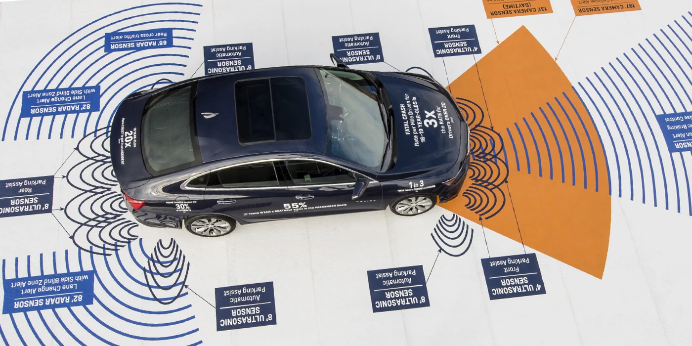
Fleet sensor calibration means checking and adjusting the sensors on your vehicles so what they report lines up with the real world. That includes GPS, IMUs, cameras, wheel speed sensors, and any other measurement hardware feeding your telematics or ADAS stack.
On a single truck, calibration might mean putting it on a rig and tweaking a few offsets. At fleet scale, it becomes a system.
You’re talking about automated checks, self-calibration algorithms running on the vehicle, over-the-air (OTA) updates for calibration parameters, and a central system that tracks calibration status, versions, and certificates for every asset. Think of it like scheduled maintenance for your data layer instead of just your hardware.
Why Sensor Calibration Is Critical for Fleet Data Quality
Once a sensor drifts, it doesn’t just “get a bit noisy.” It quietly steers every downstream decision off course. Speed governors trip when they shouldn’t. Fuel reports look odd. Predictive maintenance either cries wolf or stays silent when it matters most.
In a small fleet, you might notice this early. In a 10,000-vehicle operation, that same 2% drift corrupts millions of rows of data per day before anyone realizes something’s wrong.
Most commercial fleets now run a Bosch vehicle sensor suite or a similar package from Bosch, Continental, and other big suppliers, with aftermarket telematics hanging off CAN or OBD. That gives you GPS, IMUs, cameras, wheel speed, and a mess of CAN-derived signals.
The hardware is usually solid. The problem is that if the calibration is off, every analytic and every safety call built on that data becomes questionable.
Here’s how those calibration errors spread through a fleet in the real world:
- Speed governance: A 4 km/h bias on a speed sensor doesn’t sound like much. In practice it turns drivers who sit just under the limit into serial “speed offenders” on paper. That floods your system with false alerts and kills buy-in from crews who know they’re not actually speeding.
- Fuel and efficiency analytics: If GPS distance and odometer readings are off, your fuel-per-kilometer numbers are fiction. Vehicles can look inefficient when they’re not, or your claimed savings from a new policy can be inflated without anyone intending to fudge the numbers.
- Predictive maintenance: Miscalibrated accelerometers might scream “harsh event” every time the vehicle hits a patched road, so you waste shop time chasing ghosts. Or they under-report the real hits that crack brackets and bend components, so failures sneak up on you.
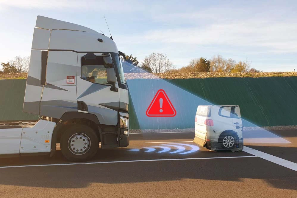
- Event reconstruction: During incident investigations, misaligned ADAS camera data and IMU traces make it hard to prove what actually happened. That weakens your position with insurers and in legal disputes even if the driver did everything right.
At scale, these aren’t random errors that average out. They’re systematic biases baked into your metrics. So fleets that are serious about raw sensor data extraction and advanced analytics have to treat calibration as part of data engineering, not an optional extra.
Fleet Sensor Types and Their Calibration Challenges
Each major sensor class has its own failure modes. You can’t manage calibration properly if you pretend a GNSS receiver, a MEMS IMU, and a camera all drift in the same way. They don’t. They drift for different reasons, at different rates, and they need different strategies.
Let’s walk through the main categories you’ll see in a modern commercial fleet: GPS and GNSS, IMUs and accelerometers, ADAS cameras, and speed or wheel sensors. CAN-derived sensors ride on top of those and inherit their problems, plus a few extra wrinkles from data extraction.
GPS & GNSS Sensors
GNSS (GPS, GLONASS, Galileo, and friends) is the anchor point for most fleet telematics. In open sky, a decent receiver gives you solid accuracy, especially if you add GPS RTK correction or one of the SBAS/PPP services.
People get burned whenever they assume “it’s GPS, it must be right” and stop thinking about calibration and error handling.
Key GPS calibration and accuracy challenges you actually run into on the road:
- GPS multipath error: In dense cities, signals bounce off glass and concrete. That “urban canyon error” can easily jump several meters while your marketing brochure still talks about open sky accuracy under 1 meter. If your system doesn’t understand and bound that error, speed and location-based rules start misbehaving.
- Clock and antenna biases: Every GNSS front end has its own quirks. Hardware and antenna geometry introduce offsets that need to be understood, either at the factory or through characterization runs. Ignoring these shows up as location and timing offsets that your analytics quietly absorb as “truth.”
- Firmware updates: Vendors occasionally ship new GNSS firmware with different filters, new constellations, or bug fixes. Behavior can change in ways that aren’t obvious. You need to re-validate those receivers against a golden reference dataset or you risk unintentional step changes in your data.
- RTK correction integration: RTK makes location incredibly sharp when done right. If corrections aren’t applied consistently across the fleet, you’ll get some vehicles with centimeter-level data and others out by meters. That’s a headache for any system trying to compare performance across vehicles.
So in a fleet, “GPS calibration” usually means characterizing and bounding errors, not turning a screw. You validate receivers across different environments, document expected behavior, and apply correction tools like RTK, SBAS, or PPP consistently. You revisit calibration when you change firmware, antennas, or mounting, not every few weeks on a timetable.
IMU & Accelerometers
MEMS IMU sensors are the quiet workhorses behind dead reckoning, harsh-event detection, stability control, and a lot of ADAS capabilities. They’re also some of the most temperamental components in the stack.
Leave them unchecked long enough and they’ll happily drift into nonsense, all while still reporting very “normal-looking” numbers.
Typical IMU calibration challenges you’ll see across a commercial fleet:
- MEMS gyroscope drift: Gyros always drift. A low drift rate (°/hour) helps, but even small rates stack up. Two hours of dead-reckoning with a cheap gyro can give you several degrees of heading error, which pushes your reconstructed path off-road on a map.
- Accelerometer bias: A tiny constant offset in acceleration readings snowballs when you integrate over time. That turns into incorrect speed, distance, and “harsh event” thresholds. One of the most common issues I see is fleets blaming drivers for harsh braking that’s really just accelerometer bias.
- Temperature coefficient sensor: MEMS behavior changes with temperature. A device calibrated at 20°C in a lab can be noticeably off at -10°C on a winter morning or 60°C in a closed cab in summer. Without a good temperature coefficient model and compensation, your analytics change with the weather.
- Magnetometer hard-iron / soft-iron correction: Put a magnetometer in a vehicle, then hang tool racks, radios, or steel brackets nearby. The local magnetic environment shifts. Hard-iron effects add offsets, soft-iron effects warp the field. Both need periodic calibration, especially when vehicles are modified.
IMUs need two things: strong factory calibration and well-designed in-field calibration. At fleet scale you can’t afford to bring every vehicle in on a tight schedule, so the real goal is self-calibration logic in the unit plus analytics in the back end that can spot outliers. Those are the units you recalibrate or replace before they cause trouble.
ADAS Cameras
Forward-facing and surround-view ADAS cameras have become standard in modern fleets. They power lane-keeping, collision warnings, pedestrian detection, and they double as event cameras. They’re also fussy about alignment.
One small bump, a sloppy windscreen replacement, or a bent bracket, and all the pretty computer vision starts lying.
Key ADAS camera calibration aspects to stay on top of:
- Camera intrinsic extrinsic calibration: Intrinsics describe the lens and sensor (focal length, distortion). Extrinsics define the camera’s position and orientation relative to the vehicle. Both need to be nailed if you want lane markers, object distance, and time-to-collision to be more than educated guesses.
- Lens distortion and mounting shift: The vehicle vibrates for thousands of hours. Brackets flex. Windscreens are replaced. A few tenths of a degree doesn’t sound like much on paper. Out on the road it can move lane markings several pixels in the image, which is enough to confuse lane-keeping and driver scoring.
- Calibration rigs and procedures: Many systems rely on an ADAS camera calibration rig with target boards placed at very specific distances and angles. Others prefer dynamic calibration, where you drive a defined route under controlled conditions. Skipping steps or “making it up” in the workshop is how fleets end up with inconsistent results between depots.
If the camera extrinsics are off, all your visual geometry is off. Lane boundaries shift, following distance looks wrong, and collision warnings may come late or too often. Tools like Continental ADAS calibration packages and OEM procedures standardize the process, but they only help if you stick to them and build checks into your fleet operations.
Smart fleets are starting to add automatic misalignment detection, for example by comparing lane detection over time or looking for sudden step changes after repairs.
Speed & Wheel Sensors
Wheel speed sensors and CAN-based vehicle speed values sit at the heart of speed limits, harsh braking detection, odometer readings, and everything that depends on distance. They seem simple, which is why they get neglected. That’s a mistake.
Common speed and wheel sensor calibration issues:
- Wheel speed sensor tick count: Many systems measure pulses per revolution and then apply a calibration factor (pulses per km) to convert ticks to distance. If that factor is off, every service interval, every fuel-per-km metric, and every speed-derived analytic inherits the error.
- Tire wear impact: As tires wear, the rolling radius shrinks. Even if nothing “breaks,” the same pulse count now represents less real distance. Over a full tread life, you can slip several percent out of spec if you never touch the calibration.
- Odometer calibration factor: Some fleets trust the OEM odometer blindly. Others tweak factors in aftermarket units or ECUs. If workshops are adjusting those without a consistent standard, you’ll get regional differences that complicate benchmarking and compliance checks.
To control this, fleets need to link wheel speed calibration to the tire lifecycle. Every tire size change, retread, or major tire service should be a calibration touchpoint. And you want fleet-wide consistency requirements, such as “all odometers within ±1% across regions,” and a way to audit that across different depots and service vendors.
Calibration Drift: How Sensors Lose Accuracy Over Time
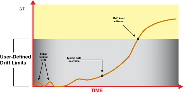
Sensors don’t suddenly “go bad” in most cases. They slowly walk away from their original calibration. That’s what catches a lot of operations off guard. The data still looks plausible on a graph, but it’s no longer telling the truth.
Calibration drift is not a sign of cheap hardware or bad engineering. It’s a physical inevitability. Heat cycles, vibration, humidity, and aging materials all push components off their original settings.
A sensible strategy assumes drift will happen, then watches for it and corrects it before it causes operational or safety problems.
Main drift mechanisms you’ll see across a working fleet:
- Thermal cycling: Vehicles sit overnight in the cold, run hot during the day, then cool back down. That expansion and contraction nudges sensor packages, solder joints, and mechanical mounts. Over thousands of cycles, characteristics shift and alignment wanders.
- Vibration and shock: Trucks and buses live in a constant vibration bath. Potholes, curbs, rough yards, and occasional impacts stress brackets, windscreens, and antenna mounts. Over time cameras sag, antennas twist a few degrees, and IMUs settle slightly off level.
- Component aging: MEMS structures, capacitors, analog front ends, and image sensors all drift as they age. Offsets creep, gain changes, and noise profiles shift. LEDs in camera modules dim. None of this is dramatic in a day, but over years it adds up.
- Firmware changes: A firmware update can change signal processing, filtering, or coordinate frames. If that isn’t revalidated and documented, you end up comparing “apples and oranges” between vehicles or over time without realizing it.
- Environmental contamination: Dirt on a camera lens, oxidation on connectors, moisture inside a housing. These don’t always look like hard failures. They just distort the signal enough to skew analytics and ADAS performance.
Some indicative drift behaviors you’ll see reported in real hardware (numbers vary by device, but the orders of magnitude are typical):
- MEMS gyroscopes: Drift rates commonly run from under 0.1°/hour on high-end units to several °/hour on low-cost parts. After a 2-hour dead-reckoning stretch, that can translate into 0.2–10° of heading error.
- Accelerometers: Bias can shift by tens of mg with temperature or age. That’s enough to meaningfully distort inferred speed and distance over long trips, especially in dead-reckoning scenarios.
- Magnetometers: Add or move steel near the sensor and the hard-iron and soft-iron profile changes overnight. The system keeps reporting a heading, but it’s now rotated relative to true.
- Cameras: A mounting angle shift of even a few tenths of a degree over months of vibration can move lane markers several pixels at longer ranges. ADAS algorithms tuned on clean lab data don’t like that.
- Wheel speed sensors: A typical 5–10 mm of tire wear between services is enough to cause a few percent error in distance if your calibration factors aren’t updated.
So a one-off workshop calibration on day one is about as useful as changing brake pads once and never touching them again. You need a living calibration strategy where sensor accuracy gets monitored, maintained, and occasionally reset, just like any other consumable in the vehicle.
Example: MEMS IMU Calibration Parameters
The table below shows typical MEMS IMU calibration-related attributes you’ll see in fleet deployments, along with how they impact day-to-day operations.
| Attribute | Typical Fleet Value | Impact on Fleet Operations |
|---|---|---|
| Drift rate (°/hour) | 0.5–5 °/hour | Higher drift makes dead-reckoning position and driver behavior analytics degrade over longer journeys, especially where GPS coverage is poor. |
| Temperature coefficient (°/°C) | 0.01–0.1 °/°C | Uncompensated temperature swings mean different bias in winter vs summer, which shows up as seasonal changes in harsh-event counts and position accuracy. |
| Calibration interval fleet (months) | 6–12 months | Shorter intervals are sensible for vehicles running extreme duty cycles, high mileage, or large temperature ranges. |
| Self-calibration capability | Yes/No | IMUs with good self-calibration routines push more of the work onto the device and reduce workshop load, especially when combined with OTA parameter tuning. |
| Cost per calibration event (USD) | $10–$100 (allocated) | Includes technician time, equipment amortization, and downtime opportunity cost, which often exceeds the raw labor rate. |
Those parameters drive your policy decisions. Higher drift rates and weak temperature compensation mean more frequent checks. Strong self-calibration and good analytics let you stretch intervals without sacrificing data quality or safety.
Automated Calibration Workflows for Large Fleets
If you try to calibrate thousands of vehicles the same way you’d handle one specialty build, you’ll bury your workshops and still fall behind. Manually lining up calibration rigs and sending every unit in “just in case” isn’t realistic at scale.
Large fleets that succeed with sensor-heavy systems design a calibration workflow from the start. They combine what the devices can do by themselves with what a central system can monitor, then push only the real problems back into the maintenance pipeline.
A practical automated calibration pipeline usually includes:
- Golden reference dataset: Build or obtain reference runs over well-surveyed routes using high-grade reference hardware. These benchmark datasets become your yardstick for validating firmware updates, new sensor models, or changed mounting locations.
- On-vehicle self-checks: Self-calibrating sensors continuously compare their outputs against models or fused estimates. For example, IMU dead reckoning is compared against GPS and wheel speed to estimate bias and drift.
- Central anomaly detection: A fleet calibration management system aggregates data, then flags vehicles whose sensor outputs statistically diverge from their peers or from the golden reference behavior.
- Parameter update workflow: Once issues are identified, updated calibration parameters are prepared, validated, and pushed to vehicles either OTA or at the next workshop visit. Every version change is logged.
- Calibration health dashboards: Operations and safety teams get a real-time view of sensor health at fleet, depot, and individual vehicle level, with alerts and trends so they can schedule interventions instead of firefighting.
This calibration lifecycle should touch your software and AI pipelines but stay logically separate from them. As covered in edge AI depends on clean data, your AI stack needs to know that calibration is versioned, audited, and stable, not silently changing underneath the models.
Self-Calibrating Sensors
Self-calibration is where you start clawing back workshop time. Modern sensor modules are smart enough to correct their own offsets and some alignment errors if you give them the right algorithms and cues.
Common self-calibration strategies used successfully in fleets:
- IMU zero-point offset: The system looks for times when the vehicle is stationary and level, such as ignition on in a depot. It then updates accelerometer and gyro offsets so “no movement” really reads as zero.
- Magnetometer correction: During low-speed turns and gentle driving, the system collects a spread of measurements and fits hard-iron and soft-iron models. That keeps heading estimates honest even as the vehicle’s magnetic environment changes.
- Wheel speed vs GPS calibration: On long, straight sections with strong GPS, the system compares wheel ticks to GPS distance. From there it refines the calibration factor (pulses per km) without a tech touching the vehicle.
- Camera auto-alignment routines: Over time, camera software can track horizons, lane markings, or known objects to spot small extrinsic misalignments. If lane centers consistently appear shifted after a windscreen swap, the algorithm can flag or partially correct that.
Self-calibration doesn’t replace the need for strong external references. What it does is stretch the interval between manual interventions and make your workshop visits far more targeted.
Resolute Dynamics’ Capture modules, for example, use normal driving and environmental patterns to keep IMU bias estimates tight so you’re not constantly pulling vehicles in just to fix drift.
OTA Calibration Updates (Process Scope Only)
Most people hear “OTA” and think of firmware, but calibration parameters are just as important to push remotely. Patching bad calibration with a laptop in a yard doesn’t scale. Using a robust OTA pipeline does.
At a high level, OTA calibration delivery supports these calibration-specific needs:
- Push new calibration parameter sets, such as IMU bias tables or camera extrinsic matrices, out to the field without waiting for scheduled maintenance.
- Keep all vehicles that share a hardware/firmware combo on a consistent calibration version, so analytics and safety policies behave predictably.
- Rollback quickly to a previous parameter set if field data shows that a new calibration behaves unexpectedly.
In disciplined fleets, each calibration parameter set is tied to particular firmware versions and hardware SKUs. That avoids situations where an update fixes one class of vehicle and breaks another because the assumptions underneath were different.
Fleet Calibration Health Monitoring
Trying to manage calibration via spreadsheets and ad-hoc notes is like trying to run a workshop without a maintenance system. It works at tiny scale, then it collapses.
A dedicated fleet calibration management system pulls calibration out into its own lane. It tracks status, exceptions, and compliance across the entire operation.
| Fleet Calibration Management Attribute | Typical Target |
|---|---|
| Vehicles per calibration technician (ratio) | 500–2,000 depending on automation level |
| Remote calibration percentage (%) | 50–90% (self-calibration + OTA parameters) |
| In-depot requirement | Only for structural changes (windscreen, major impact, hardware replacement) |
| Calibration health dashboard | Yes – per-sensor and per-vehicle status, alerts, trends |
| Compliance reporting (ISO 17025-style) | Exportable reports for audits and safety/regulatory reviews |
Fleets themselves typically aren’t ISO 17025-accredited labs, but by aligning with ISO 17025 calibration standard principles and NIST traceability concepts, you build a clean audit trail. That feeds directly into ISO safety compliance programs and gives risk and legal teams something solid to stand on when data is used as evidence.
Calibration Scheduling: How Often Should Fleet Sensors Be Recalibrated?

There’s no magic mileage number that works for everyone. Fleets that try “annual everything” or “never unless broken” end up either wasting time or flying blind. The sweet spot is a mix of time-based, event-based, and condition-based scheduling, tuned to your hardware and operating conditions.
Below are baseline intervals and triggers that work as a starting point for most large commercial fleets. You adjust from there based on what your analytics and incident data tell you.
GPS & GNSS Recalibration
- Routine interval: No strict time-based recalibration under stable conditions. Instead, run annual or semi-annual sample checks against reference data to verify that your open-sky and urban behavior still line up with expectations.
- Recalibration triggers:
- Any GPS receiver firmware update or config change that affects constellations, filters, or message formats.
- Antenna replacement, relocation, or changes in the vehicle roof layout that may affect multipath or signal quality.
- Changes in GPS RTK correction, SBAS, or PPP providers, or switching between correction service levels.
- Key checks: Compare open-sky accuracy and urban canyon error in meters against your defined bounds. Where RTK is used, verify that you consistently see centimeter-level improvements vs non-RTK behavior.
IMU & Accelerometer Recalibration
- Routine interval: Every 6–12 months for high-utilization fleets is a solid starting point. For vehicles in harsh environments, such as mining, extreme temperature regions, or rough surfaces, quarterly checks can be justified.
- Event-based triggers:
- Any significant impact, collision, or roll-over event recorded by the telematics unit.
- Bracket or mounting changes involving dashboards, roof racks, or other structures where IMUs are physically located.
- Outlier behavior flagged by fleet calibration management analytics, such as drift rates or bias patterns that diverge from the fleet norm.
- Temperature-sensitive strategy: In regions with strong seasonal swings, validate the temperature coefficient (°/°C) behavior at least twice a year, around the transition to summer and winter, to keep compensation curves up to date.
ADAS Camera Recalibration
OEMs and tier-one suppliers usually define strict rules for ADAS camera calibration, and ignoring those is where a lot of fleets get burned. Folding those rules into your fleet policies keeps your legal and safety teams much happier.
| ADAS Camera Calibration Attribute | Typical Value |
|---|---|
| Calibration type | Static (rig/targets) or dynamic (driving routine) |
| Trigger events | Windscreen replacement, camera mount change, major front impact, persistent ADAS faults |
| Calibration time (minutes) | 20–60 minutes depending on system |
| Equipment required | Target board(s), alignment tools, or defined driving route |
| Accuracy requirement | Lane and object detection typically require pixel-level precision |
Suggested policy that works well in practice:
- Always recalibrate ADAS cameras after windscreen replacement, any camera removal or relocation, and any moderate or severe front-end damage.
- Run an annual verification on a small sample at each depot, say 5–10% of the local fleet, to catch systematic workshop errors or tool misalignment.
- Use self-diagnostic metrics from the ADAS ECU, such as alignment quality flags or lane detection confidence, as condition-based triggers for extra checks.
Speed Sensor & Odometer Recalibration
Wheel speed and odometer calibration is easiest to keep tight if you tie it directly to tire management. That way your maintenance system drives calibration instead of hoping someone remembers.
| Speed Sensor Calibration Attribute | Typical Value |
|---|---|
| Calibration factor (pulses per km) | Device- and vehicle-specific; stored in ECU/telematics unit |
| Tire wear impact (% error per mm tread loss) | Often 0.3–0.8% per 5 mm, depending on tire size |
| Recalibration trigger | Tire size change, substantial tread wear, axle swap |
| Correction method | Automatic (GPS reference) or manual (service tool entry) |
| Fleet-wide consistency requirement | Within ±1–2% tolerance across vehicles |
Practical policy recommendations:
- Recalibrate whenever tire size changes, wheels are swapped across axles with different roles, or at major tire service milestones.
- Use long-run GPS comparisons whenever possible to refine calibration factors automatically, then lock those into ECUs or telematics units.
- Regularly audit depots. Differences in practice or tools can easily turn into region-wide speed and distance biases that nobody spots until analytics start to disagree.
How Resolute Dynamics Maintains Sensor Accuracy at Scale
Resolute Dynamics designs its systems specifically for sensor calibration at scale. That means thousands of vehicles, a mix of OEM hardware and aftermarket add-ons, and operations that can’t afford to have trucks sitting around waiting for a camera board to be lined up.
The approach is straightforward: automate as much calibration as the hardware will allow, detect problems early with fleet-level analytics, and then feed only the necessary work into your existing maintenance and telematics workflows. No parallel process, no mystery spreadsheets.
Capture Module Self-Calibration Routines
The Resolute Dynamics Capture platform pulls together high-grade IMUs, GNSS, and interfaces to cameras and speed sensors. The firmware isn’t just logging data. It’s actively looking after its own calibration.
- Continuous IMU bias estimation: The Capture unit uses stationary detection, knowledge of typical vehicle dynamics, and sensor fusion across IMU, GPS, and wheel speed to constantly refine gyroscope and accelerometer offsets.
- Dynamic wheel speed factor adjustment: As vehicles run known-good GPS segments, Capture compares wheel ticks to GPS distance and nudges the pulses-per-km factor into tighter alignment.
- Magnetometer calibration: During normal driving, Capture collects enough heading variation to maintain hard-iron and soft-iron calibration, while filtering out short-lived magnetic disturbances from things like overhead power lines or parked equipment.
In practice this engine means fewer trips into the shop just to chase drift. It also means that a new unit can “settle in” to its environment without a long manual calibration routine, which matters when you’re installing hardware across a large and diverse fleet.
Fleet-Wide Anomaly Detection for Drift
On the back end, a central calibration management layer uses everything the vehicles send home to spot the outliers. That’s the part most fleets miss when they focus only on individual rigs and calibration boards.
- Cross-fleet baselining: The system learns normal patterns for each sensor type by vehicle class, duty cycle, and depot. That gives you realistic expectations instead of generic lab numbers.
- Drift detection: Vehicles whose IMU drift rates, accelerometer biases, or GPS error patterns move beyond acceptable bounds are tagged. You don’t wait for a driver to complain that “ADAS feels weird.”
- Event correlation: Detected anomalies are correlated with events like collisions, workshop visits, firmware rollouts, or component changes. This makes it easier to identify systemic issues instead of treating every case as an isolated fault.
This combination turns calibration management from a reactive exercise into a proactive one. Instead of dealing with noisy metrics months after the fact, you get notified that “this subset of vehicles sees rising bias” while there’s still time to roll them through scheduled maintenance in an orderly way.
Calibration Parameter Deployment & Workflow Integration
Resolute’s deployment approach respects the fact that most fleets already have telematics, OTA, and maintenance systems in place. Calibration should work with those, not fight them.
- Version-controlled calibration sets: Every change to IMU, camera, or wheel speed calibration lives as a versioned set, linked to specific firmware and hardware IDs. That gives you full traceability for audits and incident reviews.
- Maintenance system integration: When analytics flag an issue or an event like a windscreen replacement occurs, the system can automatically raise calibration tasks in your maintenance scheduler. Techs see calibration alongside the rest of the job card, instead of as an overlooked afterthought.
- Audit-ready records: Per-vehicle calibration histories, including timestamps, methods, and references to any ISO 17025/NIST-traceable standards used, can be exported for insurers, regulators, or internal safety teams.
All of this recognizes a simple truth: edge AI depends on clean data. You can invest millions in models and still get bad outcomes if your sensors are lying. Treating calibration as a first-class part of data governance is how you avoid that trap.
Common Mistakes in Fleet Sensor Calibration (and How to Fix Them)
Most fleets don’t lose data quality because they bought bad hardware. They lose it because of predictable process mistakes. Here are the ones I see again and again, along with fixes that actually work in practice.
Mistake 1: Treating Calibration as a One-Time Workshop Activity
Problem: Vehicles get “calibrated” at installation or after a big repair, then nobody touches the settings for years unless something obviously breaks.
Risks: Small drifts compound over time. Alerts slowly get noisier, analytics get less trustworthy, and ADAS performance degrades so gradually that people just accept it as normal.
Fix: Put calibration on a schedule. Use a mix of time-based (for example annual checks for cameras or IMUs) and event-based triggers like impacts, tire changes, and windscreen replacements. Back it all with a calibration management system that shows which vehicles are compliant and which ones are overdue.
Mistake 2: Ignoring Temperature and Environment Effects
Problem: Sensors are calibrated on a bench or in mild conditions, but the vehicles work in deserts, snow, or constant start-stop traffic with extreme heat soak.
Risks: Seasonal swings in data quality. Winter data doesn’t match summer data. Harsh-event counts, dead-reckoning accuracy, and even ADAS false-positive rates change with the weather.
Fix: Measure and model temperature coefficient sensor behavior. Enable online temperature compensation where the hardware supports it. In high-variance climates, schedule seasonal verification runs to see how far sensors drift across temperature extremes and adjust your calibration strategy accordingly.
Mistake 3: No Fleet-Wide Consistency Checks
Problem: Each depot or installation partner does calibration “their way” using different tools or shortcuts. Nobody’s watching the overall pattern.
Risks: You end up with regionally skewed speed and distance metrics, inconsistent ADAS performance, and headaches when you try to compare KPIs across branches.
Fix: Standardize procedures and define fleet-level acceptance bands such as ±1–2% odometer error. Use a centralized fleet calibration management view to compare depots, and track KPIs such as vehicles per calibration technician and remote calibration percentage to see where process improvements are needed.
Mistake 4: Over-Reliance on Factory Calibration
Problem: Teams assume that whatever left the supplier’s line is “good forever,” regardless of how or where it’s mounted.
Risks: IMUs installed at odd angles, cameras tilted slightly by brackets or windscreen curvature, GPS antennas in high-multipath spots. The factory calibration doesn’t cover any of those vehicle-specific effects.
Fix: Treat factory calibration as a starting point only. Use in-vehicle verification against golden reference datasets to check that sensors behave correctly once installed, then tune extrinsic parameters and mounting-specific factors where needed.
Mistake 5: Mixing Calibration with Raw Data Protocol Issues
Problem: Teams mix up physical calibration errors with data extraction problems like wrong scaling factors or mis-decoded CAN signals.
Risks: You waste time recalibrating sensors when the real problem is a broken mapping between OBD-II and CAN, or vice versa. Different teams blame each other, and issues linger.
Fix: Separate the concerns. Sensor calibration covers physical measurement accuracy. Extraction and decoding are handled in your data pipeline and telematics configuration, as discussed in extraction accuracy needs calibration-aware mapping. Keep the processes linked but tracked independently so you always know which side you’re fixing.
Mistake 6: No Calibration Traceability for Safety Use Cases
Problem: Sensor data is used to support disciplinary actions, insurance claims, or legal defenses, but there’s no reliable record of how those sensors were calibrated.
Risks: In court or with regulators, your data can be challenged and discounted. Internally, safety teams may hesitate to rely on metrics that they can’t fully defend.
Fix: Build calibration certificate traceability into your processes. Log when, how, and by whom calibration was performed, and reference any ISO 17025/NIST-traceable standards used. Keep those records for the life of the vehicle, especially for sensors tied to speed governance and ADAS functions that are covered by ISO safety compliance expectations.
FAQ: Fleet Sensor Calibration at Scale
Below are straight answers to the questions that usually come up once fleets start thinking seriously about calibration instead of treating it as an afterthought.
How much does fleet sensor calibration cost per vehicle?
For a single calibration event, you’re typically in the range of $20–$200 per vehicle, depending on sensor type and local labor. That includes technician time, equipment, and a slice of downtime.
Spread across a year, most fleets see $10–$100 per sensor class per year. The real money, though, isn’t the direct cost. It’s what miscalibration does to fuel optimization, false speed-governance alerts, missed maintenance, and claims. One mismanaged incident or poorly defended claim can wipe out years of calibration spend in a heartbeat.
Can calibration be done remotely, or must vehicles visit depots?
A surprising amount can be handled remotely. IMU zero-point offsets, wheel speed factor refinement, and some camera alignment checks are ideal for self-calibration and OTA parameter updates.
You still need in-depot calibration for physical changes such as windscreen replacements, major structural repairs, or hardware swaps that affect mounting geometry. Mature fleets tend to land with 50–90% of calibration adjustments handled remotely, keeping depot time for the jobs where a physical rig or target board is unavoidable.
Are there regulatory or standards requirements for fleet sensor calibration?
Requirements vary by country and application, but the direction of travel is clear. More regulators and courts are expecting fleets to show traceable, documented calibration if they’re using sensor data for speed governance, ADAS, or incident reconstruction.
You’re usually not required to hold ISO 17025 accreditation yourself, but aligning your processes with ISO 17025 ideas and NIST traceability principles gives you a strong story to tell in audits and supports broader ISO safety compliance work.
What happens if we skip sensor calibration for a few years?
You rarely see a dramatic “everything fails at once” moment. What you get instead is a slow, quiet slide. Speed readings creep away from reality, ADAS warnings get less reliable, driver scores feel unfair, and analytics-based initiatives don’t deliver the expected results.
In a large fleet, that kind of death by a thousand cuts can sink electrification planning, undermine safety programs, and weaken your position with insurers during negotiations. You can also end up exposed in legal cases where the other side questions your data and you have no solid calibration records to back it up.
How mature are self-calibrating sensors for commercial fleets?
For many MEMS IMUs, wheel speed calibration routines, and basic camera quality checks, self-calibrating features are already production-ready. Plenty of fleets are running them today without drama.
They perform best as part of a system that also includes anomaly detection, controlled reference data, and periodic in-depot verification for edge cases. Self-calibration can dramatically cut manual effort, but it shouldn’t be your only line of defense where safety or liability is on the line.
Does calibration affect edge AI and advanced analytics performance?
Yes, directly. AI models learn whatever patterns you feed them. If your sensors are biased, the model treats that bias as normal. That leads to skewed risk scores, unreliable predictions, and driver assessments that don’t match what’s really happening on the road.
Since edge AI depends on clean data, robust calibration workflows are not optional add-ons. They’re part of the foundation your models stand on. Without them, you’re spending money to get very sophisticated answers to the wrong questions.
How do golden reference datasets fit into calibration at scale?
A golden reference dataset is your “truth set.” It’s a carefully collected batch of drives, environments, and labeled outcomes captured with high-accuracy, well-calibrated equipment over surveyed routes.
Fleets use golden references to validate sensor behavior after firmware changes, to benchmark new hardware or mounting locations, and to train or test anomaly detection algorithms. They help you distinguish between real-world changes (like a new road layout) and pure sensor degradation or misconfiguration.
Is calibration the same as data extraction or protocol decoding?
No. They live in different layers of your stack. Calibration deals with physical measurement accuracy, such as how many pulses per km equal a real kilometer. Data extraction and decoding deal with how you read and interpret those signals from the vehicle network, whether via OBD-II or native CAN with correct scaling and IDs.
Both must be right for clean data. For protocol and extraction considerations, see raw sensor data extraction. For sensor calibration at scale, the concepts and strategies here give you the missing half of the puzzle.
Final Summary: Building Trustworthy Fleet Data Through Calibration at Scale
Sensor calibration at scale is not just an engineering curiosity. It’s a core pillar of fleet data quality. As you add more ADAS features, deploy edge AI, and push analytics deeper into operations, any slack in calibration gets amplified fast.
GPS, IMUs, cameras, and wheel speed sensors are all subject to drift from heat, vibration, and aging. You can’t stop that. What you can do is spot it early, correct it efficiently, and prove that you did so when someone asks hard questions later.
By combining self-calibrating sensors, golden reference datasets, fleet-wide anomaly detection, and structured workflows aligned with ISO 17025 and NIST traceability concepts, large fleets can maintain trustworthy, audit-ready data across thousands of vehicles. That data is what underpins safer operations, credible driver programs, solid insurance discussions, and optimization projects that actually deliver.
If you’re ready to move off ad-hoc, “fix it when it squeaks” habits and into a designed calibration strategy, it’s worth looking at how Resolute Dynamics’ Capture platform and calibration management tooling plug into your existing telematics, maintenance, and safety systems.
This article is part of our fleet data quality series. For more, see our hub at /blog/sensor-calibration-at-scale/.